check out the new remote control Jockey Wheel SmartBar Canegrowers rearview170 Cobb Grill Skid Row Recovery Gear
Members Login
Username 
 
Password 
    Remember Me  
Post Info TOPIC: Blocking diodes in parallel


Guru

Status: Offline
Posts: 5378
Date:
Blocking diodes in parallel


I am not an electrician, and have come for advice, and not to start a flame war

I have a theory, that for the average layman, such as myself
Two lower amperage diodes in parallel, will not allow twice the amps through

I had problems trying to force 23 amps through 2 x 15SQ045 blocking diodes, as either my 20 amp DC/DC charger or the diodes were tripping, until the batteries were asking for less amps

I experimented (err playing around), using a permanent power supply of 13.5 VDC, with load of 110 watt (2 x 55 watt globes on the same wire)

I  measured just over 9 amps, with an el cheapo clamp meter, at the globes
I had two 20SQ045 diodes in parallel, each showing (before connecting them), a voltage drop of 0.140 (140 ma) using a 9 volt multimeter on diode function, with same length wires

Diodes 3mm apart
One diode showing just over 7 amps with temperature of 56șC
One diode showing just over 2 amps with temperature of 34șC

Diodes wrapped together in a cocoon of Scotch Self-Fusing Silicone Rubber Electrical Tape, to try and give each diode the same temperature
One diode showing just under 6 amps with one side of the cocoon after 30 minutes  48șC
One diode showing just over 3 amps one side of the cocoon after 30 minutes  38șC

I have come to the conclusion (my theory), that for me as a layman, I would not trust two lower value diodes in parallel, to allow higher amperage through.
I believe that one diode will trip, the amps will then go through the second diode, which will then trip.

Would be happy if the experts could prove my theory wrong, and explain (in laymen speak), why it is wrong


__________________

Tony

It cost nothing to be polite


Guru

Status: Offline
Posts: 1461
Date:

DIODE.1.JPGPANEL.JPGCURRENT.1.JPGTEMP, Diode AMB 25degC.JPGThat's why I went ths way using dual shottky diodes bolted to the each solar panel frame, theres 4 X 160W panels used.


Attachments
__________________
D.L.Bishop


Guru

Status: Offline
Posts: 1927
Date:

Hi Tonysmile

You learn things by doing and then you remember it biggrin

It is true that using two(or more) semiconductors in parallel is not as straight foward as it looks. To do that in practice they usually use 'matched' item from the same batch or take some steps with resistances in series to ensure that they share the current better. And the temperature control is important as well. hmm 
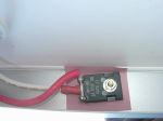
Using dual diode packages is a good way to do it. 

Use three or four they are cheap aww Solder them each end with short leads, equal length, to  copper strips to act as heat sinks which will keep them at closer temperatures and dissipate the heat so they do not run so hot anyway.   

Jaahn


-- Edited by Jaahn on Tuesday 20th of November 2018 10:22:40 AM

__________________


Guru

Status: Offline
Posts: 1315
Date:

You were doing well until you got to this bit
"I have come to the conclusion (my theory), that for me as a layman, I would not trust two lower value diodes in parallel, to allow higher amperage through.
I believe that one diode will trip, the amps will then go through the second diode, which will then trip."
Just a wrong assumption and further testing by increasing the voltage and the current would have revealed the true nature of what was happening. Diodes do not trip, they get hot and pass more current until they approach saturation in terms of current flow (amps) compared to their rating, then the voltage drop increases and at that point the easiest path would be through the diode with the least voltage drop. Electricity will always flow through the easiest path.
Getting the temperatures closer together will help with the difference in voltage drop, but not eliminate it completely, one diode will always carry a higher current load than the others. You can see this theory crossing over into real life by the difference of 7 amps through diode 1 and 2 amps through diode 2 when the temperatures were not closely match and changes to 6 amps through diode 1 and 3 amps through diode 2 when the temperatures were closer matched. The other thing revealed is that the diode carrying more current will get hotter than the diode carrying the lesser current. This will always happen unless there are resistors included in each leg so the voltage drop is balanced across all the diodes in the group. A step in the wrong direction where we want to minimise voltage drop, so doubling up on the diodes so the load is shared so no single diode gets pushed to failure point, and attempts to balance out and also dissipate the heat will mean a longer life for the diodes.

T1 Terry

__________________

You can lead a head to knowledge but you can't make it think. One day I'll know it all, but till then, I'll keep learning.

Any links to any sites or products is not an endorsement by me or do I gain any financial reward for such links 


Guru

Status: Offline
Posts: 5378
Date:

Thanks to the three of you (Daryl, Jaahn, Terry), for your input, it is appreciated

My problem of not enough solar, is now solved, as I had been assuming that the numbers I was reading, were correct

The explanation is in another post, on this forum
The link is below

https://thegreynomads.activeboard.com/t65105600/misinterpreting-battery-volt-readings-from-solar-panel/

To test the two 15 amp diodes in parallel, (thanks again fro that Terry), for the roof solar, and two 12 amp diodes in parallel, for the portable solar panel
I ran the batteries down to about 12.4 volts, with the solar panels isolated
I connected the solar panels around noon

As I had never seen over 14 amps from the roof solar panel, I was surprised to see over 17 amps, on my clamp meter
At this amperage the 15 amp diodes clicked off, for about 15 seconds, slowly built up (about 20 seconds) to over 17 amps again, then clicked off again, etc

I isolated the roof, and connected my portable panel for a few hours
With the battery no longer asking for high amps, the roof solar was giving 13 amps, and the portable panel was giving 6 amps

I now have one 20 amp, (20SQ045 HV Schoktty) diode, on both the roof and portable solar panel wires at the regulator, going through independent circuit breakers

Doing my research, (err...playing around for a week or so), discharging my batteries, and then switching the solar on at noon
I find, that I now have the luxury of having too much solar, for my 20 amp DC/DC charger/regulator

I have seen over15 amps from the roof, and over 7 amps from the portable solar panels
At 22 amps the DC/DC charger clicks off for a few seconds, and then builds up to 22 amp, and switches off again, etc

My work around shall be, (proven with experimenting, err playing around).
I can isolate the portable solar panel, or isolate both panels, and run the engine until the batteries are asking for less than 20 amps, then run both solar panels

Hope that this info is useful to someone in the future


__________________

Tony

It cost nothing to be polite


Guru

Status: Offline
Posts: 1315
Date:

You might find the "clicking off" is the solar regulator and not a function of the diodes. To verify this, do the same test but once you note the "click off" occurring, by pass the regulator and feed directly to the battery while monitoring the battery voltage and charging current and see if it still "clicks off"
Another interesting thing will be to multiply the battery voltage by the current and see just how many watts are being produced by the solar. You can go even further if you wish and divide that figure by the advertised solar capacity and this will give you the percentage efficiency of your solar set up. In full sun with the batteries close to 14.4v, don't surprised to see more than the 70% efficiency that is put forward by those promoting a different type of solar controller wink
I just had a similar thing happening with an MPPT controller that was part of an inverter/charger. It would reach a certain charging input and then stop, then slowly increase again until the same output was reached. The problem ended up being the battery voltage the MPPT output sensed was higher than the actual battery voltage due to the high current and exceeding the max battery voltage set in the MPPT control window. By simply increasing that maximum by 2v the problem was cleared and the charging current continued to climb until it plateaued and varied up and down as is part of the normal operation of an MPPT controller.


T1 Terry


__________________

You can lead a head to knowledge but you can't make it think. One day I'll know it all, but till then, I'll keep learning.

Any links to any sites or products is not an endorsement by me or do I gain any financial reward for such links 


Guru

Status: Offline
Posts: 5378
Date:

Hi Terry

My clamp meter was on the cable, between the solar panel and the 20 amp DC/DC regulator, and showing just over 17 amps when the power stopped, (diodes click off), which of course turned the solar panel off

With the single 20 amp diode fitted, there is now no interruption, from the solar panel, when it reached 17 amps, which is obviously only under testing, when I deliberately run the batteries down 

I would be unwilling to bypass the DC/DC charger/regulator, and go direct to the battery, (to check the watts), due to the high (minimum 19.5) volts of the solar panel, at the inlet of the DC/DC regulator
300 watt roof solar panel, but (17 amps times 19.5 volts) having a calculated wattage of 331, means that either I have an exceptional solar panel, (switched the panel on at noon), or my instruments have lived up to their name of el cheapo

I had more or less decided that the clicking off was not the 20 amp DC/DC regulator, because I can get up to 20 amps, from the solar panels in parallel, without any clicking off, of the volts/current

I am happy with my current situation of having a 20 amp diode on both positive output lines of my solar panels, just before the DC/DC regulator, going through independent circuit breakers

My days of being a smile Signtist smile, (err...looking at/for the signs), are over, until I find another problem

I have another technical question, which I have put up on another post, which I am asking the techies to answer, without starting any flame wars

Link is below

https://thegreynomads.activeboard.com/t65115894/cable-square-area-compared-to-fuse-or-diode-square-area/

Once again thanks to everyone for their input


__________________

Tony

It cost nothing to be polite


Guru

Status: Offline
Posts: 1927
Date:

Hi Tony,smile

I am with Terry here about the clicking. I have never heard a diode clicking and there is nothing in a diode to make noise. Normally when they make a noise the smoke comes out confuse and they never turn on again. Something else is switching off somewhere else.

Jaahn  


__________________


Guru

Status: Offline
Posts: 5378
Date:

smilesmilesmile If I do not laugh at myself over this, then no one else will smilesmilesmile

I have egg all over my face again

I have used the wrong word, with my hearing aid turned off, I would not hear clicking, if it fell out of my hand, and onto my foot

I used the word clicking as a figure of speech

Perhaps I should said
When I noticed 17 amps on my el cheapo clamp meter, I then almost immediately noticed nothing
Nothing meaning zero on the clamp meter, and no lights on the DC/DC regulator, indicating when there is any incoming, or outgoing, power

Not sure if there is a click, when the CTEK DC/DC regulator turns off, probably is, but I doubt if I had heard it, or I could have heard it subconsciously

Sorry for any misprinting on my part


__________________

Tony

It cost nothing to be polite


Guru

Status: Offline
Posts: 1315
Date:

The cutting of the solar current when using 2 x 15 amp diodes compared to using a 20 amp diode is interesting. I'm guessing the voltage drop once the 17 amps was reached was enough for the CTek DC to DC controller to switch off as it deemed the solar voltage was too low. When the 20 amp diode was installed the voltage drop was less so the solar controller remained active until it reached its 20 amp limit. The fact the CTek solar part of the DC to DC controllers is so inefficient, yet you still get 20 amps output, says the solar part is working very well.

T1 Terry

__________________

You can lead a head to knowledge but you can't make it think. One day I'll know it all, but till then, I'll keep learning.

Any links to any sites or products is not an endorsement by me or do I gain any financial reward for such links 


Guru

Status: Offline
Posts: 5378
Date:

T1 Terry wrote:

The cutting of the solar current when using 2 x 15 amp diodes compared to using a 20 amp diode is interesting. I'm guessing the voltage drop once the 17 amps was reached was enough for the CTek DC to DC controller to switch off as it deemed the solar voltage was too low. When the 20 amp diode was installed the voltage drop was less so the solar controller remained active until it reached its 20 amp limit. The fact the CTek solar part of the DC to DC controllers is so inefficient, yet you still get 20 amps output, says the solar part is working very well.

T1 Terry


 I had just gave a longish post, and after clicking submit, told invalid key please submit post again, so here goes another post, hope it comes through
Sorry to have taken so long to reply

The cutting of the solar current when using 2 x 15 amp diodes compared to using a 20 amp diode is interesting. I'm guessing the voltage drop once the 17 amps was reached was enough for the CTek DC to DC controller to switch off as it deemed the solar voltage was too low. When the 20 amp diode was installed the voltage drop was less so the solar controller remained active until it reached its 20 amp limit

Never thought of that, Terry. This gave me a bit of food for thought, over the last few days

I have since found
The DC/DC solar side of the regulator is suppose to work from 11.5 volts up to 23 volts
This means theoretically, that I would have to obtain around 26 amps, for the voltage to drop to less than 11.5
I have no idea, or the means to measure, if the speed of the voltage drop, would affect the DC/DC regulator, as the battery would probably have been saying, gimmy, gimmy, or words to that effect

I have done some experimenting, (err...playing around) today

Ran batteries down to 12.6 volts, and took three readings over about ninety minutes
Readings were taken between 20 amp diode, and DC/DC regulator, there would have been more amps going to the batteries, through the MPPT DC/DC regulator
11.20 amps @ 15.66 volts (175 watts from solar panel) through calculations, not measurements
9.31 amps @ 16.30 volts (151 watts from solar panel) through calculations, not measurements
8.22 amps @ 16.51 volts (135 watts from solar panel) through calculations, not measurements

I can now see that higher amps from the solar panel, will result in lower volts, so I can therefore follow your reasoning

The fact the CTek solar part of the DC to DC controllers is so inefficient, yet you still get 20 amps output, says the solar part is working very well.

In order to originally make sure, that the 15 amp diodes (in parallel) would work
I put my hand up here, and say that I had never before seen 17 amps from my roof solar panel, and assumed that 14 amps was the best I would get
I had run the batteries down, and switched on the roof solar panel, at noon
This scenario, would have given the solar panel, its best opportunity, to show what it was capable of

Today, I did not expect to see high amps for two main reasons

  • The batteries were full when I isolated the 300 watt roof solar panel, and ran the batteries down to 12.6 volts
  • I did not connect the roof solar panel until well after noon, it would have been partly shaded by the air con, and there were some wispy clouds around

I hope that this makes sense

My gut feeling, (without any proof), is that for me as a layman, it is better that I use one larger than required (20 amp) diode, than two smaller (15 amp) ones, which may or may not carry the full amps


__________________

Tony

It cost nothing to be polite


Guru

Status: Offline
Posts: 1315
Date:

Just for clarification, was it one of the double 20 amp diodes with a connection across both inputs similar to the one DB posted, or a single 20 amp diode? Very interesting findings though, but I still don't understand why the charging would stop at 17 amps through the 2 parallel 15 amp diodes, still something not right that caused that to happen. It is good to see you have sorted the solar problems and hopefully this will also help other members here to sort any solar problems

T1 Terry


-- Edited by T1 Terry on Friday 30th of November 2018 03:26:21 PM

__________________

You can lead a head to knowledge but you can't make it think. One day I'll know it all, but till then, I'll keep learning.

Any links to any sites or products is not an endorsement by me or do I gain any financial reward for such links 


Guru

Status: Offline
Posts: 5378
Date:

It was a single 20 amp Schottky diode, Terry

20SQ045 HY

Same type, same number, (except for 20 instead of 15), as the ones you gave to me


__________________

Tony

It cost nothing to be polite

Page 1 of 1  sorted by
 
Quick Reply

Please log in to post quick replies.

Tweet this page Post to Digg Post to Del.icio.us
Purchase Grey Nomad bumper stickers Read our daily column, the Nomad News The Grey Nomad's Guidebook