check out the new remote control Jockey Wheel SmartBar Canegrowers rearview170 Cobb Grill Skid Row Recovery Gear Caravan Industry Association of Australia
Members Login
Username 
 
Password 
    Remember Me  
Post Info TOPIC: Custom 6x20 watts solar setup with MPPT


Guru

Status: Offline
Posts: 3994
Date:
RE: Custom 6x20 watts solar setup with MPPT


Whenarewethere wrote:

I tried covering each 1/3 of the panels & the total power dropped only by exactly 1/3 according to the Victron app, & covered 2/3 or the panels & power was down by exactly 2/3. I also did 3 panels in series in 2 sets & power dropped by half.


 This would suggest that very little current, if any, is being back-fed into the shaded panels. If so, then are blocking diodes really necessary?


__________________

"No friend ever served me, and no enemy ever wronged me, whom I have not repaid in full."

Lucius Cornelius Sulla - died 78 BC 


Guru

Status: Offline
Posts: 7323
Date:

In this situation probably not worth the effort with diodes. But one would need to test there own setup. Maybe if they are larger panels it's a different story.


If one packs all the actual solar cells together (Photoshop) they take up 72.7% of the panel. So 155 watts/m2. The larger the panel, the border will be a smaller percentage of the panel area.

I've got up to 137 watts water cooled midday / 6 panels = 22.8 watts a panel, so 176 watts/m2 if they were as close as the Photoshop arrangement. May be they would improve a touch more if I took the glass off the panel.

But you do need a frame & space between cells & glass.

_MG_1837-73percent.jpg

_MG_1837.jpg


Attachments
__________________

Procrastination, mankind's greatest labour saving device!

50L custom fuel rack 6x20W 100/20mppt 4x26Ah gel 28L super insulated fridge TPMS 3 ARB compressors heatsink fan cooled 4L tank aftercooler Air/water OCD cleaning 4 stage car acoustic insulation.


Guru

Status: Offline
Posts: 3994
Date:

Whenarewethere wrote:

If one packs all the actual solar cells together (Photoshop) they take up 72.7% of the panel. So 155 watts/m2. The larger the panel, the border will be a smaller percentage of the panel area.


 In retrospect my original calculation was stupid. Your calculation seems right on the mark.


__________________

"No friend ever served me, and no enemy ever wronged me, whom I have not repaid in full."

Lucius Cornelius Sulla - died 78 BC 


Guru

Status: Offline
Posts: 1315
Date:

The border around the panel edge reaches a practical limit. The lip required for the aluminium frame to hold the glass will not only cast a shadow in any but the perfect sun to panel angle, the lip also produces an area around the edges of the panel that collect dirt build up after rain when the panel is flat mounted. As you have already seen, any shadow or reduced light through the glass even at a very fine line along the edge, will virtually stop any output from the panel.
Some panels have a ridiculously big border but generally this can be traced back to smaller modules being used to build a panel that looks to be the same size and area, a common Chinese manufacturing trick, the true output of the panel is less than the panel with the correct size modules, but a sticker is easy to print and near impossible for the average user to dispute the figures displayed on the label.
If the panel measures the same dimensions then forget about trying to get a PayPal claim against the seller.


But none of this changes the fact that those panels you say are 20w panels put out a lot more than 20w, so the claim you are getting X output from 120w of solar panels I misleading.

T1 Terry


Another point I missed in the photo-shopped image, you can not reduce the gap between the modules much more than the way they are on the panels, the space is needed to solder the tabs and add an isolation layer to separate the negative from the positive. 


-- Edited by T1 Terry on Sunday 10th of November 2019 06:01:51 PM

__________________

You can lead a head to knowledge but you can't make it think. One day I'll know it all, but till then, I'll keep learning.

Any links to any sites or products is not an endorsement by me or do I gain any financial reward for such links 


Guru

Status: Offline
Posts: 1315
Date:

Whenarewethere wrote:

I've wired the panels back to parallel once & back to series again. I'm not doing it another time, besides the Kyoritsu 2046R clamp meter confirms the Victron output. I use the clamp meter on holidays to do random checks & I can't complain with what is going into the batteries.

This photo from the top of the thread when the panels were all in parallel showed 7.5amps going into the MPPT which corresponds to the panel meter.

Probably 2 controllers, clamp meter & panel meter are all faulty.

IMG_3547.jpg


Who knows, it seems to be a complete mystery just what is being measured. One minute you are measuring the voltage of 2 panels in series, then there is a meter reading of 4.1 amps and a reading with 4 cable loops showing 16.7 amps, and now a reading of 7.5 amps. If the clamp meter and 2 controllers and a Victron all read the same, just which "same" do they read, 7.5 amps or 4.1 amps? Then there is a post about 11.6 amps a while back .... getting a bit like the fisherman's tale .....


T1 Terry


__________________

You can lead a head to knowledge but you can't make it think. One day I'll know it all, but till then, I'll keep learning.

Any links to any sites or products is not an endorsement by me or do I gain any financial reward for such links 


Guru

Status: Offline
Posts: 7323
Date:

Whenarewethere wrote:

But you do need a frame & space between cells & glass.


 As I said you need a space. If you have large cells the gap will be a smaller percentage.


__________________

Procrastination, mankind's greatest labour saving device!

50L custom fuel rack 6x20W 100/20mppt 4x26Ah gel 28L super insulated fridge TPMS 3 ARB compressors heatsink fan cooled 4L tank aftercooler Air/water OCD cleaning 4 stage car acoustic insulation.


Guru

Status: Offline
Posts: 1315
Date:

Whenarewethere wrote:

But you do need a frame & space between cells & glass.


 As I said you need a space. If you have large cells the gap will be a smaller percentage.


We at least agree on that one. On one had, the greater output the panel is, the more efficient harvest to sq area is, but the other side is any shadow across the panel has a much greater effect to the total output compared to multiple panels that make up the same panel output. For roof top solar, the big panel makes more sense, for RV use, especially roof mounted, a smaller panel within reason makes more sense. Much below 60w does bring the wasted area into play a lot more, but the smaller panels mounted across the roof area where some panels will be shaded during part of the day, but not shaded other parts of the day, all contributes to an over greater harvest over the full day.

Spot measurements are very misleading, it is the total harvest across the whole day that tells the true story.


T1 Terry  


__________________

You can lead a head to knowledge but you can't make it think. One day I'll know it all, but till then, I'll keep learning.

Any links to any sites or products is not an endorsement by me or do I gain any financial reward for such links 


Guru

Status: Offline
Posts: 3994
Date:

T1 Terry wrote:

Who knows, it seems to be a complete mystery just what is being measured. One minute you are measuring the voltage of 2 panels in series, then there is a meter reading of 4.1 amps and a reading with 4 cable loops showing 16.7 amps, and now a reading of 7.5 amps. If the clamp meter and 2 controllers and a Victron all read the same, just which "same" do they read, 7.5 amps or 4.1 amps? Then there is a post about 11.6 amps a while back .... getting a bit like the fisherman's tale ....


AIUI, 7.5A was generated by the panels when all 6 were wired in parallel. That's 1.25A per panel. 

The 4.1A reading was taken when the panels were wired as "2 in series x 3 sets with no diodes", so that's about 1.4A per panel.

Looping the cable 4 times through the clamp meter gave a reading of 16.7A, which confirms that the meter is reasonably linear.

When the OP says "same", I take it to mean that the reading reported by each device for the same parameter are identical. For example, if the clamp meter is measuring 4.1A at the panels, then the Victron is reporting 4.1A at its input.

In fact I'm quite grateful to the OP for having taken the time to perform these measurements. I can appreciate that it's not a trivial thing to rewire his setup for each experiment.


__________________

"No friend ever served me, and no enemy ever wronged me, whom I have not repaid in full."

Lucius Cornelius Sulla - died 78 BC 


Guru

Status: Offline
Posts: 7323
Date:

Series setup:

4.1amps is 2 panels in series x 3 sets with the setup as one whole array short circuited (As currently wired).

7024113565117088295.jpg


Parallel setup:

7.5 amps when the panels were in parallel with power going into the MPPT, so not short circuited (As previously wired).

1428069227276187087.jpg

This photo is the actual battery voltage & amps between the panels (all 6 in parallel) & the MPPT. (Readings match my clamp meter)

IMG_3534.jpg

I apologise for the childish drawings hopefully my solar panel wiring diagrams are clear.


Attachments
__________________

Procrastination, mankind's greatest labour saving device!

50L custom fuel rack 6x20W 100/20mppt 4x26Ah gel 28L super insulated fridge TPMS 3 ARB compressors heatsink fan cooled 4L tank aftercooler Air/water OCD cleaning 4 stage car acoustic insulation.


Guru

Status: Offline
Posts: 7323
Date:

dorian wrote:

In fact I'm quite grateful to the OP for having taken the time to perform these measurements. I can appreciate that it's not a trivial thing to rewire his setup for each experiment.


 I am a person who quadruple checks things & from as many different angles as possible. Not simply repeating the same thing. If something does not add up I straight away assume where have I stuffed up.

I have also checked voltages with my 2 other multimeters but I limited to 10amps.


__________________

Procrastination, mankind's greatest labour saving device!

50L custom fuel rack 6x20W 100/20mppt 4x26Ah gel 28L super insulated fridge TPMS 3 ARB compressors heatsink fan cooled 4L tank aftercooler Air/water OCD cleaning 4 stage car acoustic insulation.


Guru

Status: Offline
Posts: 3994
Date:

T1 Terry wrote:
For roof top solar, the big panel makes more sense, for RV use, especially roof mounted, a smaller panel within reason makes more sense. Much below 60w does bring the wasted area into play a lot more, but the smaller panels mounted across the roof area where some panels will be shaded during part of the day, but not shaded other parts of the day, all contributes to an over greater harvest over the full day.  

The OP states that he uses no diodes. I personally would follow conventional practice and use both bypass diodes and blocking diodes. 

Projecta's installation guide states that their SPP20 20W panel does not have an integral bypass diode, so ISTM that shading would be a real problem for his "2 panels in series" setup.

https://static1.squarespace.com/static/5939e22ac534a5226114de77/t/59910cf8ff7c500cdedf9e35/1502678272120/SPP20-135_instruction_Issue2.pdf


-- Edited by dorian on Sunday 10th of November 2019 07:42:19 PM

__________________

"No friend ever served me, and no enemy ever wronged me, whom I have not repaid in full."

Lucius Cornelius Sulla - died 78 BC 


Guru

Status: Offline
Posts: 7323
Date:

To date I just move it around in the sun, it's not exactly that I need to have it out all day as the fridge only used 12 - 15AH per 24 hours & charge the odd phone.


__________________

Procrastination, mankind's greatest labour saving device!

50L custom fuel rack 6x20W 100/20mppt 4x26Ah gel 28L super insulated fridge TPMS 3 ARB compressors heatsink fan cooled 4L tank aftercooler Air/water OCD cleaning 4 stage car acoustic insulation.


Guru

Status: Offline
Posts: 1315
Date:

Thankyou for the explanation of what each reading was measuring, makes sense now and I apologies for my mistakes due to assuming the reading were from a single pair of panels rather than the whole array . Still can't figure out how you get 136w after the MPPT losses and cabling losses from a 120w solar array, but maybe there was some special circumstances that were not revealed at the time.

Ok, now I understand your set up better, if you are looking to improve the output over the long term such as for a full day rather than spot readings, Ill recommend the following changes. Totally up to you if you want to implement them or not.
If you rewire the array as 3 panels in series and 2 sets in parallel, the voltage drop between the array and the controller will drop and become a miniscule percentage of the overall loss.
Next, link the output of panel 1 and panel 4 in parallel, the same for panel 2 and panel 5 and finally, panel 3 and panel 6. This will deliver the most possible output from the 2 series/parallel strings because both series strings have their panels balanced with the other string. This way, a shadow on one panel will not drop the voltage of that string to less than the voltage of the other string, both strings will see the same voltage and perform at their best accounting for the loss of 1 panel.

T1 Terry

__________________

You can lead a head to knowledge but you can't make it think. One day I'll know it all, but till then, I'll keep learning.

Any links to any sites or products is not an endorsement by me or do I gain any financial reward for such links 


Guru

Status: Offline
Posts: 7323
Date:

I went with 2 panels next to each other in series otherwise it will not close fully.

Or I would have to drill a hole in the top end of each frame near the hinging side for wiring & that would be in the way of the cradle the panels sit in on the roof rack.

All the legs are anodised aluminium & 304 stainless M4 countersunk bolts & a few Allen bolts, with Nyloc nuts. Aluminium was tapped as well. Nylon hinges with stainless pin. 

6371564769217906407.jpg

2636330134453651482.jpg

3342018575494502543.jpg


Attachments
__________________

Procrastination, mankind's greatest labour saving device!

50L custom fuel rack 6x20W 100/20mppt 4x26Ah gel 28L super insulated fridge TPMS 3 ARB compressors heatsink fan cooled 4L tank aftercooler Air/water OCD cleaning 4 stage car acoustic insulation.


Guru

Status: Offline
Posts: 3994
Date:

T1 Terry wrote:

If you rewire the array as 3 panels in series and 2 sets in parallel, the voltage drop between the array and the controller will drop and become a miniscule percentage of the overall loss.


Next, link the output of panel 1 and panel 4 in parallel, the same for panel 2 and panel 5 and finally, panel 3 and panel 6. This will deliver the most possible output from the 2 series/parallel strings because both series strings have their panels balanced with the other string. This way, a shadow on one panel will not drop the voltage of that string to less than the voltage of the other string, both strings will see the same voltage and perform at their best accounting for the loss of 1 panel.


 What are the current paths in such an arrangement? Maybe I'm having a brain fart, but I can't seem to make sense of it.


__________________

"No friend ever served me, and no enemy ever wronged me, whom I have not repaid in full."

Lucius Cornelius Sulla - died 78 BC 


Guru

Status: Offline
Posts: 1315
Date:

dorian wrote:
T1 Terry wrote:

If you rewire the array as 3 panels in series and 2 sets in parallel, the voltage drop between the array and the controller will drop and become a miniscule percentage of the overall loss.


Next, link the output of panel 1 and panel 4 in parallel, the same for panel 2 and panel 5 and finally, panel 3 and panel 6. This will deliver the most possible output from the 2 series/parallel strings because both series strings have their panels balanced with the other string. This way, a shadow on one panel will not drop the voltage of that string to less than the voltage of the other string, both strings will see the same voltage and perform at their best accounting for the loss of 1 panel.


 What are the current paths in such an arrangement? Maybe I'm having a brain fart, but I can't seem to make sense of it.


panel 1 is the first panel in series string 1 & panel 4 is the first panel in series string 2 so this parallels the 2 panels, shade on one will pull the output of the other down but not by 50% as one would assume. The same for the other panels connected in parallel as well as series. The result is both series strings will be at the same voltage and output capability so both strings will supply the MPPT controller not just one string.


As for the panels being connected in pairs. If it is possible to parallel panel 1 and 3, panel 2 and 4, panel 3 and 6, this will have a similar result as far as shade tolerance, but the 3 panels in series would work better over all.


T1 Terry 


__________________

You can lead a head to knowledge but you can't make it think. One day I'll know it all, but till then, I'll keep learning.

Any links to any sites or products is not an endorsement by me or do I gain any financial reward for such links 


Guru

Status: Offline
Posts: 7323
Date:

It is easy to visualise 6 panels in a circle.

A shadow tends to appear from one side. If panel 6 has some shadow you still have the same voltage with panel 3, but half the current as 6 is dead.

Hopefully one has moved the array, but as the shadow moves across panel 5 will be in the shade but panel 2 is still providing the voltage, but only half the current as 5 is dead.

1667126567808424736.jpg

With 1 panel in the shade in this arrangement are you getting 5/6 of the amps or 1/2 the amps?


-- Edited by Whenarewethere on Monday 11th of November 2019 06:10:24 PM

Attachments
__________________

Procrastination, mankind's greatest labour saving device!

50L custom fuel rack 6x20W 100/20mppt 4x26Ah gel 28L super insulated fridge TPMS 3 ARB compressors heatsink fan cooled 4L tank aftercooler Air/water OCD cleaning 4 stage car acoustic insulation.


Guru

Status: Offline
Posts: 3994
Date:

Let's reduce the question to an absurd hypothetical case.

Let's say you have a 12V, 200W panel in series with a 12V, 20W panel.

Both panels have an open circuit voltage of 40V. Their short circuit currents are 13A and 1.3A, respectively.

At MPP, when tested on their own, both panels have the same voltage, say 18V. Their MPP currents are 11A and 1.1A, say.

When connected in series, their combined O/C voltage is 80V. However, what current flows when the series pair is short circuited? Does the larger panel push 13A through the smaller panel?

At MPP, in full sunlight, what voltage and current does the array produce?


__________________

"No friend ever served me, and no enemy ever wronged me, whom I have not repaid in full."

Lucius Cornelius Sulla - died 78 BC 


Guru

Status: Offline
Posts: 3994
Date:

ISTM that, if you don't use bypass diodes, then the combined voltage of two panels would appear in reverse across the shaded panel. Surely that must be a bad thing?

              +V            +V
              -->           -->
           .-------.     .-------.
           |       |     |       |
     .-----|  #1   |-----|  #2   |-----.
     |     |       |  V  |       | 2V  |
     |     '-------'     '-------'     |
   ^ |                                 |  |
   | | Isc                             |  | Isc
   | |                                 |  v
     |     .-------.                   |
     |     |/ / / /| 2V                |
  0V '-----|/ #3 / |-------------------'
           |/ / / /|
           '-------'
             <--
             -2V


__________________

"No friend ever served me, and no enemy ever wronged me, whom I have not repaid in full."

Lucius Cornelius Sulla - died 78 BC 


Guru

Status: Offline
Posts: 1315
Date:

Even though the shaded panel has next to no current, it still produces voltage. In a parallel array, as long as there is an alternate path for the to drain the current the shaded panel will not suffer a reverse current flow. It is only when there is no current drain the stronger panels can overcome the weaker panel and burn it out.
In a series connection array, there is a real danger of forcing the current through a shaded panel so a bypass diode is a bit of insurance against that happening. Bypass diodes don't rob any of the voltage unless they are acting as a bypass because the shaded panel may not produce enough current to increase the voltage on the output compared to the input.
Now we come to the third scenario, 2 or more panels in a parallel arrangement also in a series array. Now all the panels in parallel would need to be shaded for those panels to be subject to the possibility of a reverse current flow. If only one of the panels in the parallel arrangement is in the sun, both panels would be seen as being producing some output and therefore it would not suffer reverse current flow. Because there is a difference between the input and output voltage, the current path could be compared to being lubricated to improve the flow .... yeah I know, terrible analogy :lol:

T1 Terry

T1 Terry

__________________

You can lead a head to knowledge but you can't make it think. One day I'll know it all, but till then, I'll keep learning.

Any links to any sites or products is not an endorsement by me or do I gain any financial reward for such links 


Guru

Status: Offline
Posts: 3994
Date:

This is the proposed array working at its maximum power point, namely 6 x Vmp x Imp.


             .-------.   .-------.   .-------.
         Imp |       |Imp|       |Imp|       |
           .-|  #1   |-+-|  #2   |-+-|  #3   |-.
           | |       | | |       | | |       | |
    0V o---+ '-------' | '-------' | '-------' +---o + 3Vmp
           | .-------. | .-------. | .-------. |
   2Imp    | |       | | |       | | |       | |       2Imp
           '-|  #4   |-+-|  #5   |-+-|  #6   |-'
        Imp  |       |Imp|       |Imp|       |
             '-------'   '-------'   '-------'
                -->         -->         -->

               +Vmp        +Vmp         +Vmp


Let's block out panel #6. Now the array looks like this, with current from panels #4 and #5 being diverted through panel #3 ...


             .-------.   .-------. ->    -> .-------.
         Imp |       |Imp|       |Imp   2Imp|       | 2Imp
           .-|  #1   |-+-|  #2   |----+-----|  #3   |----.
           | |       | | |       |    | ^   |       |    |
    0V o---+ '-------' | '-------'    | |   '-------'    +---o + 3Vmp
           | .-------. | .-------.    | Imp .-------.    |
   2Imp    | |       | | |       | -> |     |///////|    |       2Imp
           '-|  #4   |-+-|  #5   |----+-----|//#6 //|----'
        Imp  |       |Imp|       |Imp   I=0 |///////| I=0
             '-------'   '-------'          '-------'
                -->         -->                -->

               +Vmp        +Vmp                +Vmp


... but clearly this is absurd because the output of the array would be 3 Vmp x 2 Imp = 6 x Vmp x Imp. That is, 5 panels would now be producing the same output as 6 panels. So what really happens in practice?

In fact the above scenario reduces to an 80W panel (36V x 2.2A) in series with a 20W panel (18V x 1.1A). So the 80W array is trying to push 2.2A through a 1.1A, 20W panel. That can't be good ???

If we block out both panels #3 and #6, then the result is essentially identical to the 3-panel example I drew earlier. That's not good, either.

Here is another thought experiment. Assume we have one 20W panel producing 18V @ 1.1A in full sunlight, and a second identical, but partly shaded, panel producing 14V @ 0.7A (10W). What happens to the current and voltage when we connect them in series?


-- Edited by dorian on Tuesday 12th of November 2019 02:42:58 PM

__________________

"No friend ever served me, and no enemy ever wronged me, whom I have not repaid in full."

Lucius Cornelius Sulla - died 78 BC 


Guru

Status: Offline
Posts: 3994
Date:

@Whenarewethere, if you shade one cell in one of your panels, do you lose all the output from that panel? If so, then all 36 cells must be wired in series with no bypass diodes. Otherwise, I suspect that each sub-string of 12 cells may have its own bypass diode, in which case you could only kill the entire output by shading one cell in each sub-string.
 
 
A shadow falling on a small part of a panel can have a surprisingly large effect on output. Not only will the cells that are shaded be producing less power, but as the cells within a panel are normally all wired in series, the shaded cells affect the current flow of the whole panel.
 
 
Some solar panels are constructed with the cells divided into groups, each group having a built-in by-pass diode.

Here is an interesting resource which demonstrates that partial shading can cause hot spot related damage in the shaded cells. Bypass diodes can mitigate the damage, but not always.

https://www.dupont.com/content/dam/dupont/products-and-services/solar-photovoltaic-materials/solar-photovoltaic-materials-landing/documents/hot-spot-mitigation.pdf

The authors state that they have encountered cases where diode protection was not effective.

In this example, we dismantled the junction box to examine the interior. We found visually undamaged bypass diodes; however, the diodes were unable to prevent the hot spot that damaged the backsheet. In this case, the bypass was not triggered, showing either that the diode did not function as expected or that the diode had not reached the designed reverse bias for operation. In all cases, the non-operation of the bypass should be considered as a failure.


-- Edited by dorian on Tuesday 12th of November 2019 04:42:41 PM

__________________

"No friend ever served me, and no enemy ever wronged me, whom I have not repaid in full."

Lucius Cornelius Sulla - died 78 BC 


Guru

Status: Offline
Posts: 7323
Date:

If I shade one cell it stops the whole panel.

I can see the wiring of all 36 cells & they are all in series & the positive & negative terminals are on the back of the panel. Very simply wired.


__________________

Procrastination, mankind's greatest labour saving device!

50L custom fuel rack 6x20W 100/20mppt 4x26Ah gel 28L super insulated fridge TPMS 3 ARB compressors heatsink fan cooled 4L tank aftercooler Air/water OCD cleaning 4 stage car acoustic insulation.


Guru

Status: Offline
Posts: 3994
Date:

Whenarewethere wrote:

If I shade one cell it stops the whole panel.

I can see the wiring of all 36 cells & they are all in series & the positive & negative terminals are on the back of the panel. Very simply wired.


That's interesting. If I understand what I've read on various web sites, the shaded cell would be reverse biased by the other unshaded cells. In full sunlight, and if no reverse current were flowing, the shaded cell would see the sum of the open circuit voltages of 35 cells, which you have measured at 21V. Once reverse current starts to flow, the shaded cell would look like a resistor and begin to heat up. If it gets hot enough, it can blister the backsheet. Worse still, if you have 3 panels in series, with no bypass diodes, then a single unshaded cell would be reverse biased by 63V.

The following paper discusses this phenomemnon, but I don't fully understand it.

Investigation of the Relationship between Reverse Current of Crystalline Silicon SolarCells and Conduction of Bypass Diode:
downloads.hindawi.com/journals/ijp/2012/357218.pdf


__________________

"No friend ever served me, and no enemy ever wronged me, whom I have not repaid in full."

Lucius Cornelius Sulla - died 78 BC 


Guru

Status: Offline
Posts: 3994
Date:

This paper is interesting. It has thermal images of hot spots in a batch of solar cells biased at -10V.

Operational behaviour of commercial solar cells under reverse biased conditions:

http://citeseerx.ist.psu.edu/viewdoc/download?doi=10.1.1.128.325&rep=rep1&type=pdf

The researchers took 10 cells from a particular panel and plotted their reverse I-V characteristics. The result was a huge range. For example, the currents at a reverse bias of 15V varied from about 0.5A to 2.5A.

They state that "bypass diodes concepts of 18 to 24 cells per bypass diode are commonly used, yielding a maximum reverse voltage in the range -10 V to -13 V".

ISTM that, in the worst case, any shaded cell must be able to dissipate the combined maximum power output of the entire sub-string. AISI, if you were to short circuit your panel and shade one cell, and because your panel has no bypass diodes, then you would risk burning out the shaded cell.


__________________

"No friend ever served me, and no enemy ever wronged me, whom I have not repaid in full."

Lucius Cornelius Sulla - died 78 BC 


Guru

Status: Offline
Posts: 1315
Date:

dorian wrote:

This is the proposed array working at its maximum power point, namely 6 x Vmp x Imp.


             .-------.   .-------.   .-------.
         Imp |       |Imp|       |Imp|       |
           .-|  #1   |-+-|  #2   |-+-|  #3   |-.
           | |       | | |       | | |       | |
    0V o---+ '-------' | '-------' | '-------' +---o + 3Vmp
           | .-------. | .-------. | .-------. |
   2Imp    | |       | | |       | | |       | |       2Imp
           '-|  #4   |-+-|  #5   |-+-|  #6   |-'
        Imp  |       |Imp|       |Imp|       |
             '-------'   '-------'   '-------'
                -->         -->         -->

               +Vmp        +Vmp         +Vmp


Let's block out panel #6. Now the array looks like this, with current from panels #4 and #5 being diverted through panel #3 ...


             .-------.   .-------. ->    -> .-------.
         Imp |       |Imp|       |Imp   2Imp|       | 2Imp
           .-|  #1   |-+-|  #2   |----+-----|  #3   |----.
           | |       | | |       |    | ^   |       |    |
    0V o---+ '-------' | '-------'    | |   '-------'    +---o + 3Vmp
           | .-------. | .-------.    | Imp .-------.    |
   2Imp    | |       | | |       | -> |     |///////|    |       2Imp
           '-|  #4   |-+-|  #5   |----+-----|//#6 //|----'
        Imp  |       |Imp|       |Imp   I=0 |///////| I=0
             '-------'   '-------'          '-------'
                -->         -->                -->

               +Vmp        +Vmp                +Vmp


... but clearly this is absurd because the output of the array would be 3 Vmp x 2 Imp = 6 x Vmp x Imp. That is, 5 panels would now be producing the same output as 6 panels. So what really happens in practice?

In fact the above scenario reduces to an 80W panel (36V x 2.2A) in series with a 20W panel (18V x 1.1A). So the 80W array is trying to push 2.2A through a 1.1A, 20W panel. That can't be good ???

If we block out both panels #3 and #6, then the result is essentially identical to the 3-panel example I drew earlier. That's not good, either.

Here is another thought experiment. Assume we have one 20W panel producing 18V @ 1.1A in full sunlight, and a second identical, but partly shaded, panel producing 14V @ 0.7A (10W). What happens to the current and voltage when we connect them in series?


-- Edited by dorian on Tuesday 12th of November 2019 02:42:58 PM


The shaded panel can not produce current unless the voltage is at the relevant Vmp. If the system pulls the voltage lower, all the panels in the string will be pulled low proportionally.  This happens when the MPPT controller decides a lower voltage might harvest more current because the hotter panel has a lower Vmp. It only finds out by trial and error, so the panel voltage is a constantly changing, no one panel drops its voltage but rather all the series string is dropped proportionally .... getting your head around that one can be mind blowing when you consider each panel could/will be at a different temperature and therefore the Vmp will be a different voltage.

I attended a promotional afternoon event at Tindo Solar in adelaide yesterday and put that one to the rep from the inverter company they use in their grid tie system and battery backed systems ... talk about getting tongue tied trying to answer until he finally came up with the "get out of jail line" I'd have to refer you to our engineers for a more technical explanation :lol:  There was a number of reps that adapted that line .... There was one that was selling an individual panel output optimiser that just loved my question because it played right into his sales pitch biggrin 
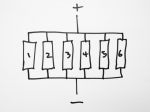
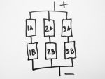
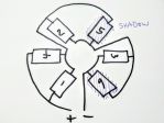
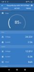
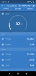
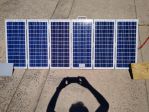
There were a few raised eyebrows when I mentioned match battery voltage to the possible voltage range of the series solar string and powering the inverter from there ........
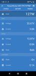
 

T1 Terry


T1 Terry 


__________________

You can lead a head to knowledge but you can't make it think. One day I'll know it all, but till then, I'll keep learning.

Any links to any sites or products is not an endorsement by me or do I gain any financial reward for such links 


Guru

Status: Offline
Posts: 1315
Date:

dorian wrote:

This paper is interesting. It has thermal images of hot spots in a batch of solar cells biased at -10V.

Operational behaviour of commercial solar cells under reverse biased conditions:

http://citeseerx.ist.psu.edu/viewdoc/download?doi=10.1.1.128.325&rep=rep1&type=pdf

The researchers took 10 cells from a particular panel and plotted their reverse I-V characteristics. The result was a huge range. For example, the currents at a reverse bias of 15V varied from about 0.5A to 2.5A.

They state that "bypass diodes concepts of 18 to 24 cells per bypass diode are commonly used, yielding a maximum reverse voltage in the range -10 V to -13 V".

ISTM that, in the worst case, any shaded cell must be able to dissipate the combined maximum power output of the entire sub-string. AISI, if you were to short circuit your panel and shade one cell, and because your panel has no bypass diodes, then you would risk burning out the shaded cell.


At that Tindo event, they showed us around the factory where they produce the panels from the basic components. Each module is light tested looking for micro fractures before being placed in the series string for soldering them together, then each string is placed on the sticky layer that is on the glass panel, these are soldered together with a busbar type assembly cut and soldered from a continuous roll of the silver foil strip, then it goes to a thermal imagine unit that pushes a reverse current through the modules to check for any bad joints or modules. Once it passes that stage it has a second sticky layer applied and the backing sheet and then spends 20 mins in bake oven. Then goes to a surface inspection station, then has the edges trimmed, silicon applied to the inside raiis of the frame, that frame then attached to the edges of the glass panel, the corners bevelled and touched up to avoid sharp edges, then the silicon is applied and the junction box fitted and each tape from the busbar ribbons is locked into the junction block terminals, it then goes to another surface inspection point were any small blemishes are clean off the glass, then to a light box and the output is tested to determine it is plus the rated output, it is reject of not, then it goes to the stacker and onto a pallet.

Well worth the visit is you are ever in Adelaide, amazing to watch the process, the number of human checkers in the robot production line to ensure the quality is maintained to eliminate any under production issues and just how many panel they produce at such a high quality.


T1 Terry   


__________________

You can lead a head to knowledge but you can't make it think. One day I'll know it all, but till then, I'll keep learning.

Any links to any sites or products is not an endorsement by me or do I gain any financial reward for such links 


Guru

Status: Offline
Posts: 7323
Date:

Out doing some tests, panels about 12° off square to the sun.

No cells covered: 127 watts. (After test 3° 129 watts)

1 cell covered on 1 of the series sets: 85 watts.

1 cell covered on 2 of the series sets: 46 watts.

1 cell covered on 3 of the series sets: 53 watts.

I tried covering 9 cells on 1 panel & it dropped to the same as if only 1 cell was covered on 1 panel.

96301491611325016.jpg

1645337891105760696.jpg

7473904733253722996.jpg

1805933582102219719.jpg

7751352105517442468.jpg

1326498546067459976.jpg


Attachments
__________________

Procrastination, mankind's greatest labour saving device!

50L custom fuel rack 6x20W 100/20mppt 4x26Ah gel 28L super insulated fridge TPMS 3 ARB compressors heatsink fan cooled 4L tank aftercooler Air/water OCD cleaning 4 stage car acoustic insulation.


Guru

Status: Offline
Posts: 7323
Date:

Looking at the figures for '1 cell covered on 3 of the series sets 53 watts.'

The input current has gone up to 3.4 amps but the voltage has dropped to 15.8 volts. So it would be a good idea to use diodes in at least this situation so half the panels are working at full capacity.

I may as well do it properly while at it.

I would appreciate if someone would advise me which bypass & blocking diodes are best.


__________________

Procrastination, mankind's greatest labour saving device!

50L custom fuel rack 6x20W 100/20mppt 4x26Ah gel 28L super insulated fridge TPMS 3 ARB compressors heatsink fan cooled 4L tank aftercooler Air/water OCD cleaning 4 stage car acoustic insulation.


Guru

Status: Offline
Posts: 7323
Date:

I'll get these Schottky diodes if they are ok. https://www.jaycar.com.au/diode-1n5822-schottky-40v-3a-d027-pack-10/p/ZR1023


__________________

Procrastination, mankind's greatest labour saving device!

50L custom fuel rack 6x20W 100/20mppt 4x26Ah gel 28L super insulated fridge TPMS 3 ARB compressors heatsink fan cooled 4L tank aftercooler Air/water OCD cleaning 4 stage car acoustic insulation.

«First  <  1 2 3 4  >  Last»  | Page of 4  sorted by
 
Quick Reply

Please log in to post quick replies.

Tweet this page Post to Digg Post to Del.icio.us
Purchase Grey Nomad bumper stickers Read our daily column, the Nomad News The Grey Nomad's Guidebook