check out the new remote control Jockey Wheel SmartBar Canegrowers rearview170 Cobb Grill Skid Row Recovery Gear Caravan Industry Association of Australia
Members Login
Username 
 
Password 
    Remember Me  
Post Info TOPIC: Ideal Diodes and Primer on Solar Charge Controls


Guru

Status: Offline
Posts: 3978
Date:
Ideal Diodes and Primer on Solar Charge Controls


I found this primer. The author provides several circuit examples. 

A Primer on Solar Charge Controls:

https://www.electroschematics.com/10679/primer-solar-charge-controls/

I also found this 30A PWM regulator:

http://oatleyelectronics.com//product_info.php?cPath=21&products_id=1145

The datasheet claims that "there are no Schottky isolation diodes that would dissipate around 10W at 10A! Instead a MOSFET/S configured with extra circuitry to serve as an 'ideal diode' that dissipates only 1W at 10A."

http://oatleyelectronics.com/files/IT119-120-1213050W.pdf

Has anyone checked inside their own regulator to see whether the design uses an "ideal diode"?


__________________

"No friend ever served me, and no enemy ever wronged me, whom I have not repaid in full."

Lucius Cornelius Sulla - died 78 BC 


Guru

Status: Offline
Posts: 1315
Date:

The problem with using mosfet/s for switching is the need for a diode across the it to protect it against back EMF (not sure if I've used the correct term there, still a bit brain dead) Once you put a diode between the output and the input you provide a path for current back flow, then you need another diode to block that and the losses start to compound. How do you protect the mosfet from the ripples caused by the rapid pulsing the PWM control causes on the solar side of the regulator. After all, the linear regulator is the only type that doesn't use PWM for voltage control and linear regulators are real battery killers in hot conditions.

T1 Terry

__________________

You can lead a head to knowledge but you can't make it think. One day I'll know it all, but till then, I'll keep learning.

Any links to any sites or products is not an endorsement by me or do I gain any financial reward for such links 


Guru

Status: Offline
Posts: 3978
Date:

What kind of switching components do your regulators use? Can the VCEsat of a BJT or IGBT go as low as the RDSon x Id of a power MOSFET?


__________________

"No friend ever served me, and no enemy ever wronged me, whom I have not repaid in full."

Lucius Cornelius Sulla - died 78 BC 


Guru

Status: Offline
Posts: 1464
Date:

1.JPG2.JPG3.JPG4.JPG


Attachments
__________________
D.L.Bishop


Guru

Status: Offline
Posts: 1464
Date:

Have several of these 30A regulators as they were cheap & do the job required. Theres 3 MOSFETs on the underside of the board, I assume one is the PWM reg the other is the isolator & the 3rd one is programed to switch the load on/off. I use 3 x 160W solar panels with it @ max of 25Amps.


__________________
D.L.Bishop


Guru

Status: Offline
Posts: 3978
Date:

Thanks for the photos. The datasheet/manual states that the "ideal diode" is comprised of a MOSFET plus additional circuitry. I can only see U2 in the immediate vicinity. Can you tell us the markings on this chip?

BTW, this design does not use a buck regulator to smooth the PWM pulses. Is there any evidence that charging the battery with high current pulses reduces its life when compared with a buck regulator?


__________________

"No friend ever served me, and no enemy ever wronged me, whom I have not repaid in full."

Lucius Cornelius Sulla - died 78 BC 


Guru

Status: Offline
Posts: 1933
Date:

dorian wrote:

Thanks for the photos. The datasheet/manual states that the "ideal diode" is comprised of a MOSFET plus additional circuitry. I can only see U2 in the immediate vicinity. Can you tell us the markings on this chip?

BTW, this design does not use a buck regulator to smooth the PWM pulses. Is there any evidence that charging the battery with high current pulses reduces its life when compared with a buck regulator?


Hi Dorian smile

A PWM regulator just switches the current on and off. The battery capacity smooths the output. Been like that since solar panels were used. That is why they are simple and effective. No fancy electronics to fail. 

If you are looking for that extra small part of a volt for your battery charging them just buy another panel !! 

Jaahn


__________________


Guru

Status: Offline
Posts: 1464
Date:

Will have to get back later on what the MOSFETs are, as I need to remove them to see. Just checked the current draw when theres no solar charge at night at 10Ma.

__________________
D.L.Bishop


Guru

Status: Offline
Posts: 3978
Date:

Jaahn wrote:
A PWM regulator just switches the current on and off. The battery capacity smooths the output. Been like that since solar panels were used. That is why they are simple and effective. No fancy electronics to fail. 

The author of the primer defines a PWM regulator as any that uses Pulse Width Modulation. He is of the opinion that those PWM regulators which are based on a buck topology are preferable to the "cheap, inferior" inductorless types. That's why I asked whether pulsed charging is best avoided.

BTW, I'm more concerned about battery life than extra volts or Ah. Sunlight is cheap, batteries aren't.


-- Edited by dorian on Friday 4th of January 2019 10:38:13 AM

__________________

"No friend ever served me, and no enemy ever wronged me, whom I have not repaid in full."

Lucius Cornelius Sulla - died 78 BC 


Guru

Status: Offline
Posts: 3978
Date:

DeBe wrote:

Will have to get back later on what the MOSFETs are, as I need to remove them to see. Just checked the current draw when theres no solar charge at night at 10Ma.


Please don't go to all that trouble. I'm just curious about the IC at U2.

Here is an example of an "ideal diode" IC:

https://www.analog.com/media/en/technical-documentation/data-sheets/4357fd.pdf


__________________

"No friend ever served me, and no enemy ever wronged me, whom I have not repaid in full."

Lucius Cornelius Sulla - died 78 BC 


Guru

Status: Offline
Posts: 1464
Date:

2.JPG1.JPGThey are definitely MOSFETS as there leads are marked S D & G. But cant find any data on those particular type numbers.


Attachments
__________________
D.L.Bishop


Guru

Status: Offline
Posts: 1315
Date:

dorian wrote:

Thanks for the photos. The datasheet/manual states that the "ideal diode" is comprised of a MOSFET plus additional circuitry. I can only see U2 in the immediate vicinity. Can you tell us the markings on this chip?

BTW, this design does not use a buck regulator to smooth the PWM pulses. Is there any evidence that charging the battery with high current pulses reduces its life when compared with a buck regulator?


 The complete opposite actually. That pulse charging extends lead acid battery life and brings lithium batteries to 100% SOC much faster. The author of that article has some strange views of how things actually work. This for instance

The typical 12V (nominal) solar panel puts out about 18V NL (No-Load) in full sunlight. If this solar panel is connected directly across a 12V battery, it will attempt to charge it to the no-load voltage,

That 18v is the point a typical 12v solar panel can produce its max current at 25*C internal temp when mounted on a flash light box, the open circuit voltage is the no load voltage but of course a solar panel can not charge to the no load voltage because it doesn't produce any current at that voltage.

Then this bit

Solar controls also include a reverse polarity diode to prevent the battery from discharging into the solar panel under low light conditions.

The Mosfet does that, the diode is to protect the mosfet from back EMF spiking it beyond its capability. The second diode could be to block the snubber diode from any reverse current flow but I'd imagine they use different circuitry for that.

This is the circuitry of a solid state relay and very similar to how the PWM circuit works, note the snubber diode across the mosfet.

Solid state relay internal circuit.jpg


T1 Terry


Attachments
__________________

You can lead a head to knowledge but you can't make it think. One day I'll know it all, but till then, I'll keep learning.

Any links to any sites or products is not an endorsement by me or do I gain any financial reward for such links 


Guru

Status: Offline
Posts: 1464
Date:

These are the ICs on the regulator, The processor chip is under the LCD display8.JPG


Attachments
__________________
D.L.Bishop


Guru

Status: Offline
Posts: 3978
Date:

My Web searches don't turn up any definitive conclusions regarding the benefits or downsides of pulse charging. The only consensus appears to be that pulse charging can punch through sulfate deposits or "resistive barriers", and these phenomena appear to be due to undercharging, or prolonged storage, or excessive float or trickle charging. Correct me if I'm wrong, but I don't believe that there are any pulse charging implementations for lithium batteries in consumer appliances.
 
As for the MOSFET chopper, it has a body diode which provides the path for the battery to discharge into the panel. The "ideal diode" example in the Linear Tech datasheet shows an N-channel MOSFET configured in reverse -- its source pin connects to the panel and its drain to the battery. In effect you have two MOSFETs connected back-to-back, such that their body diodes are in antiphase.
 
I suspect that the 4-pin IC at U2 may be involved with the "ideal diode" in some way.
 
BTW, I can't find any reference to the MOSFET part numbers on the Net, either.


-- Edited by dorian on Friday 4th of January 2019 02:02:10 PM

__________________

"No friend ever served me, and no enemy ever wronged me, whom I have not repaid in full."

Lucius Cornelius Sulla - died 78 BC 


Guru

Status: Offline
Posts: 1464
Date:

MOS.5.JPGMOS.1.JPGMOS.2.JPGMOS.3.JPGMOS.4.JPGThis is the N ch MOSFET on a component tester.


Attachments
__________________
D.L.Bishop


Guru

Status: Offline
Posts: 3978
Date:

The logo belongs to Alpha & Omega Semiconductor, but I can't find the MOSFETs on their web site.

http://aosmd.com/products


Edit: It's an AOT270:

http://www.aosmd.com/res/data_sheets/AOT270AL.pdf


-- Edited by dorian on Friday 4th of January 2019 10:19:07 PM

__________________

"No friend ever served me, and no enemy ever wronged me, whom I have not repaid in full."

Lucius Cornelius Sulla - died 78 BC 


Guru

Status: Offline
Posts: 1464
Date:

Thanks for finding that, dorian.


__________________
D.L.Bishop


Guru

Status: Offline
Posts: 3978
Date:

Here is a patent for an ideal diode, with specific application for solar regulators:

https://patentimages.storage.googleapis.com/d5/10/96/910f996bbeba28/US9515518.pdf

It uses an op-amp (OPA349) to control an N-channel enhancement mode MOSFET switch. I'm guessing that's the function of the SGM358 in the PWM regulator.


-- Edited by dorian on Saturday 5th of January 2019 10:39:34 AM

__________________

"No friend ever served me, and no enemy ever wronged me, whom I have not repaid in full."

Lucius Cornelius Sulla - died 78 BC 


Guru

Status: Offline
Posts: 1464
Date:

Q6-Q7 stage.JPGQ7.1.JPGQ6.1.JPGA bit more information. It appears the isolating Q7 is driven with 31.2Hz & nothing when theres no solar input. Q6 was driven by a pulse every 4 seconds to regulate the voltage as the battery was fully charged. (The rubbish on top of the wave form is noise in the CRO pre amp)


-- Edited by DeBe on Saturday 5th of January 2019 12:37:28 PM


-- Edited by DeBe on Saturday 5th of January 2019 05:03:17 PM

Attachments
__________________
D.L.Bishop


Guru

Status: Offline
Posts: 1315
Date:

From the original article:
Solar controls also include a reverse polarity diode to prevent the battery from discharging into the solar panel under low light conditions.

Thanks for that DeBe, that at least debunks this part from the original article and explains how the 2 mosfets work together to replace the blocking diode the author of the article seems to think was in there. The diodes are clearly snubber diodes, not blocking diodes.


T1 Terry


__________________

You can lead a head to knowledge but you can't make it think. One day I'll know it all, but till then, I'll keep learning.

Any links to any sites or products is not an endorsement by me or do I gain any financial reward for such links 


Guru

Status: Offline
Posts: 3978
Date:

ISTM that there are two ways to block reverse current into the panel. One is a Schottky blocking diode, while the other is a MOSFET configured as a diode. The author has chosen to illustrate his example of a PWM buck regulator using the former. He could just as easily have used the latter. In fact the "primer" appears to have been written in 2014 or earlier, and the patent I alluded to was filed in the same year, so possibly this is a relatively new idea?

As for the snubber (aka "body diode"), I doubt that it does any snubbing. Instead it is the job of the "freewheeling diode" to allow the inductor's current to dissipate after the chopper has switched off. Of course I'm referring to the buck regulator topology in the primer, so other implementations may differ. 


__________________

"No friend ever served me, and no enemy ever wronged me, whom I have not repaid in full."

Lucius Cornelius Sulla - died 78 BC 


Guru

Status: Offline
Posts: 3978
Date:

This seller is listing the same (?) regulator as an MPPT type:

https://www.ebay.com.au/itm/12V-200W-Folding-Solar-Panel-Kit-Mono-Caravan-Boat-Camping-Power-Charging/123449105637

Hmmm ...


__________________

"No friend ever served me, and no enemy ever wronged me, whom I have not repaid in full."

Lucius Cornelius Sulla - died 78 BC 


Guru

Status: Offline
Posts: 3978
Date:

I notice that the AOT270 MOSFET has a 140A current rating (110A at 100 degC). This begs the question, what are the ratings of the MOSFETs in the 10A and 20A versions of this regulator, and are there any other differences?

BTW, the RDSon is 3 mOhm at 20A, so that's a voltage drop of 90mV at 30A, or 3W. Presumably the "ideal diode" would have a similar voltage drop.

If a 200W panel delivers a maximum current of 15A, say, then the average voltage drop across the MOSFET chopper would be 45mV, and the power dissipation would be 0.7W. If we add the dissipation in the "ideal diode", then the total would be 1.4W.
 

Disclaimer:

I notice another current thread which addresses "arguments" in this subforum. I've said before that I don't understand much about solar technology, and I confess that not much has changed since then. I'm just an observer trying to distinguish between opinion and fact. To this end I'm endeavouring to understand the electronics. That's something I can get my head around. That said, I'm still trying to understand how current can flow from source to drain in an N-channel MOSFET.


Edit: Here is an earlier patent (2004) for a "solarswitch", aka ideal diode:

http://www.freepatentsonline.com/6713989.pdf


-- Edited by dorian on Sunday 6th of January 2019 07:19:44 AM

__________________

"No friend ever served me, and no enemy ever wronged me, whom I have not repaid in full."

Lucius Cornelius Sulla - died 78 BC 


Guru

Status: Offline
Posts: 1464
Date:

dorian, the 4 pin IC U2 is a EL817 opto coupler.

__________________
D.L.Bishop


Guru

Status: Offline
Posts: 3978
Date:

I'm wondering whether U2, D1 and D2 form some kind of protection circuit which alerts the microcontroller if either the panel or the battery have been connected with reversed polarity.


__________________

"No friend ever served me, and no enemy ever wronged me, whom I have not repaid in full."

Lucius Cornelius Sulla - died 78 BC 


Guru

Status: Offline
Posts: 1464
Date:

This is the 10A regulators that came on my 160W solar panels. They are certainly not what they say they are, they are PWM & not one out of 3 were any good. Mostly they failed or the voltage stayed at 15V (too high). The processor chip has no markings.REG.1.JPGREG.2.JPGREG.3.JPGREG.4.JPG


Attachments
__________________
D.L.Bishop


Guru

Status: Offline
Posts: 3978
Date:

The MOSFETs, if they are genuine, are rated for 80A at 25C (65A at 100C), and their RDSon is 7 mOhm.

http://datasheetcafe.databank.netdna-cdn.com/wp-content/uploads/2015/10/HY1707.pdf


XL2001, XLSEMI, 5V, 1.8A 150kHz 45V buck converter for USB:

http://www.xlsemi.com/datasheet/XL2001%20datasheet.pdf


__________________

"No friend ever served me, and no enemy ever wronged me, whom I have not repaid in full."

Lucius Cornelius Sulla - died 78 BC 


Guru

Status: Offline
Posts: 3978
Date:

I see lots of "MPPT" solar regulators like this one (100A):

https://www.ebay.com.au/itm/100A-MPPT-Solar-Panel-Regulator-Charge-Controller-12V-24V-Auto-Focus-Tracking-BU/292703818611

They can be had for less than AU$30. I don't for one second believe that the specs are genuine, but I'm curious as to what is inside. ISTM that a genuine MPPT controller would need to periodically monitor the panel's current and voltage. This would imply that the LCD should be able to display these data, even if they need to be selected from a menu.

BTW, I wonder what the seller/manufacturer means by "auto focus tracking". It also has "thunder protection". 

This 40A MPPT controller looks genuine (AU$60):

https://www.ebay.com.au/itm/LCD-10-20-30-40A-12V-24V-MPPT-Solar-Panel-Regulator-Charge-Controller-3Timer-YS/143055909810


-- Edited by dorian on Monday 7th of January 2019 10:00:24 AM

__________________

"No friend ever served me, and no enemy ever wronged me, whom I have not repaid in full."

Lucius Cornelius Sulla - died 78 BC 


Guru

Status: Offline
Posts: 1464
Date:

For thunder protection, probably means lightning protection. On the top set of pictures theres a blue disc by the LH of the terminal strip, its a TVS for spike protection & its across the solar terminals.

__________________
D.L.Bishop


Guru

Status: Offline
Posts: 1933
Date:

Hi Dorian smile

Your search for knowledge is admirable wink 
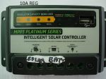
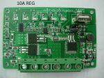
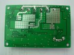
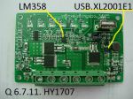
I do not claim any expertise in this area other than my reading and ownership.  I have said before that previous research has shown that lots or even most, of the cheap MPPT regulators are fakes. I have relied on other tests done in the past to compare some brands. But if you look at the size of the enclosures and the heat sinks for the units it is certainly obvious some units look and are sized like PWM regs. This applies IMHO to Australian retail offerings as well as Ebay. 

For a MPPT reg to work well it needs two functions. First function which you are pursuing, it needs to be able to take input at a higher voltage than the battery and 'convert' that to battery voltage and increase the current proportionally. That is the current gain promised by MPPT regs, but is actually just the 'buck' regulator, not the MPPT part.

The second function that is not mentioned in most advertising or elaborated on, is the actual MPPT part of the control system. There must be a 'smart' controller which will periodically 'test' the input and out put against some parameters and adjust the output to get the maximum current. This IMHO, is what sorts out a good unit that tracks fast and has a good program to extract the maximum power from the panel under all conditions and sun exposure. Indeed it is called Maximum Power Point Tracking.biggrin A poor quality unit has a very slow and clunky adjustment to the continuous changes of input and battery condition. Indeed the cheap ones probably do almost nothing in this area to track the maximum power point, or even actually nothing at all.

Of course after the battery has reached the set voltages the unit reverts to PWM regulation anyway. The extra power available is not used at all. disbelief

Jaahn        


__________________
1 2 3  >  Last»  | Page of 3  sorted by
 
Quick Reply

Please log in to post quick replies.

Tweet this page Post to Digg Post to Del.icio.us
Purchase Grey Nomad bumper stickers Read our daily column, the Nomad News The Grey Nomad's Guidebook