check out the new remote control Jockey Wheel SmartBar Canegrowers rearview170 Cobb Grill Skid Row Recovery Gear
Members Login
Username 
 
Password 
    Remember Me  
Post Info TOPIC: Avan Electrics


Senior Member

Status: Offline
Posts: 183
Date:
RE: Avan Electrics


Gooday Chris, thanks for that, I have 6m twin ran straight to the battery via a Anderson plug through a dual battery set up, and a spare switched wire in my trailer plug, all I have to do is tap into the unused reverse light wire in the van wiring and take the wires off the battery and fit terminals to these wires and plug into the Electroblock. all I need to do is find some terminals that will fit into the wiring block.

Dave

__________________
Dave


Senior Member

Status: Offline
Posts: 157
Date:

Yes! It sounds like you're on the right track. Just one question - the 'spare switched wire in my trailer plug' - what switches it on? If it is on only when the motor is running, perfect.
Did you read my private reply about our next trip? I was wondering if you could suggest a decent free camp near Walcha and Dorrigo. I have been checking Camps 6 and Wikicamps and there doesn't seem to be much choice.

I also made some suggestions how you could get the MNL contact pins so one of them should have what you need - or if you find a local supplier please let me know! And don't forget that the permanent positive to pin 6 needs a 15A fuse (a 30 amp holder was recommended) and the trigger wire to pin 5 needs a 2A fuse.

__________________

Best regards,

Chris

Licensed Electrician, Electronics, Gaming & Computer Technician. Now retired and loving it!


Senior Member

Status: Offline
Posts: 183
Date:

Yeah got everything ready, just need to buy the terminals that fit the wiring block, do you have the part number?

Thanks

Dave

__________________
Dave


Veteran Member

Status: Offline
Posts: 54
Date:

03_troopy wrote:

A query to other Avan owners:

  Has your Avan been fitted with the Elektroblock EBL 109-6 or similar battery charger, and if so, has the DC-DC function been wired in?


-- Edited by 03_troopy on Monday 26th of August 2013 08:13:17 PM


Howdy 03_troopy,

My 2012 A'Van Aspire 499 does appear to be wired in, as shown on the picture below.

There is an Anderson plug at the A frame and when I plug it into the tug, my volt meter does show a reading on red and black cables on block 2, pins 4 & 5.  When the Anderson plug is disconnected, there is no voltage showing on those pins 4 & 5.

However, I am not convinced that the Elecktroblock is actually charging the batteries in the caravan when the Anderson plug is attached, because the volt meter does not show any discernible voltage increase when the engine is started and running.  Also, I can't work out what the purple wire on block 2, pin 6 does.  I managed to trace it to underneath the kitchen sink and then it just goes somewhere I can't see, without dismantling the cabinetry.  :(

You've mentioned about the "charge control pin" on block 2 - which pin is that?

Any suggestions on how to test to see if the DC to DC function is working properly would be greatly appreciated.  Thanks in anticipation.


Lawrance


__________________

2012 A'Van Aspire 499 Adventure pack & 2009 200 Series diesel


Senior Member

Status: Offline
Posts: 157
Date:

Hi, Lawrance! From your pix, there is no doubt the DC/DC charger/booster is wired in. But they seem to have done something quite strange. According to my EBL 109-6 manual (attached), the schematic clearly identifies Block 2 - pin 6 (top row, RH end) as the main 12v feed from the trailer plug and pin 5 (top row, centre) as the charge control wire. This is also known as an ignition feed as it is only 'live' when the motor is running and is used to 'disable' high current loads when the car is parked. From the pix it would appear that the main feeds go to pins 4 and 5, and the control (smaller gauge wire) goes to pin 6. I have attached a manual with schematics so you can either check it out yourself if you are handy with a meter, or get your Avan dealer to ensure the wiring is OK. It may explain why you can't detect any charging while the engine is running. If they have swapped pins 5 and 6, and they fitted the recommended 2 amp fuse on the control wire, the fuse would be blown as the charging current is normally around 12 amps on my van when the battery voltage is low. Just so you know, when wired correctly, the EBL 109 does a great job. You may also need to check if your van wiring AND your car socket has an ignition wire connected. If not, there is a way around it. I recommend you read the previous posts on this thread. 

To summarise, you should read full charging voltage (at least 12vdc across pin 4(-ve) and pin 6 (+ve) without the motor running. When the motor is running, pin 5 (centre) should also read 12vdc (+ve). When pin 5 goes 'high' it trips a relay in the EBL 109 which energises the charger/booster module. By the way, the solar module works brilliantly well too.


-- Edited by Stratman77 on Tuesday 3rd of February 2015 12:23:31 AM


-- Edited by Stratman77 on Tuesday 3rd of February 2015 12:32:42 AM

Attachments
__________________

Best regards,

Chris

Licensed Electrician, Electronics, Gaming & Computer Technician. Now retired and loving it!


Guru

Status: Offline
Posts: 1615
Date:

tempestv8 wrote:
03_troopy wrote:

A query to other Avan owners:

  Has your Avan been fitted with the Elektroblock EBL 109-6 or similar battery charger, and if so, has the DC-DC function been wired in?


-- Edited by 03_troopy on Monday 26th of August 2013 08:13:17 PM


Howdy 03_troopy,

My 2012 A'Van Aspire 499 does appear to be wired in, as shown on the picture below.

There is an Anderson plug at the A frame and when I plug it into the tug, my volt meter does show a reading on red and black cables on block 2, pins 4 & 5.  When the Anderson plug is disconnected, there is no voltage showing on those pins 4 & 5.

However, I am not convinced that the Elecktroblock is actually charging the batteries in the caravan when the Anderson plug is attached, because the volt meter does not show any discernible voltage increase when the engine is started and running.  Also, I can't work out what the purple wire on block 2, pin 6 does.  I managed to trace it to underneath the kitchen sink and then it just goes somewhere I can't see, without dismantling the cabinetry.  :(

You've mentioned about the "charge control pin" on block 2 - which pin is that?

Any suggestions on how to test to see if the DC to DC function is working properly would be greatly appreciated.  Thanks in anticipation.


Lawrance


 Yes, as Stratman77 has said, it appears that the charge and control wire have been wired incorrectly. The small blue wire would be the control wire (confirm that it has 12V when vehicle ignition is on only) and the heavy red wire would be the 12V charge wire from the tow vehicle. So they need to be swapped so that the blue wire (if it checks out correctly) would be in the top centre of the connector (5), and the heavy red in the top right of the connector (6).  And also as Stratman77 has pointed out, they should be suitably fused as per the diagram.


__________________

Yes I am an agent of Satan, but my duties are largely ceremonial.


Veteran Member

Status: Offline
Posts: 54
Date:

Thanks for the speedy responses, guys! I have looked at the wiring schematics multiple times, and am sure that the setup isn't quite correct. That "chunky" red cable in block 2, pin 5 should be relocated to pin 6. Thanks for confirming my thoughts and supplying the PDF. I have also had a look at the block diagram of Stratman77 and it is nice and simple to understand.

I am still in the dark WRT the thin purple wire. I will redouble my efforts to look at where that purple wire goes, as I do suspect it is the trigger wire. I dismantled my 7 pin flat plug on the towing loom connector, but there was no purple wire there. So my next test would be to remove the purple wire altogether from the block connector and see what device/appliance stops working. :)

Will report back once I get a chance to look into this, hopefully tomorrow.


Stratman77 wrote:

 By the way, the solar module works brilliantly well too.


On that note, I noticed that the Block for the solar input into the Elektroblock is not used. 


The A'Van Aspire 499 solar panel came fitted with a JUTA PWM and this is how the solar panel is wired into the two house batteries.


Even though the solar panel input is not going through the Elektroblock, I think it works rather well.  So I'm happy to leave the Elektroblock out of the equation with the solar charging side of things.

I just would like to know what capacity solar panel I have on the roof.  Unfortunately there are no specs to be found on A'Van product literature.  So I have no clue as to whether the panel is a 80 Watt or 120 Watt or whatever.  confuse


-- Edited by tempestv8 on Tuesday 3rd of February 2015 07:52:07 AM

__________________

2012 A'Van Aspire 499 Adventure pack & 2009 200 Series diesel


Senior Member

Status: Offline
Posts: 157
Date:

Lawrance, If you are reading +12vdc on the purple wire and you don't have an 'ignition' wire (see the EBL 109 manual, page 4 Item 5) at the car socket and/or the motor isn't running, I don't know where they have connected it. Maybe to the fridge 12vdc connection (accessible by removing the vent panel behind it). I can't guarantee that the EBL 109 charger module will start up (the internals of the module are vague) if both pins 5  and 6 are virtually shorted out and both get +12v at the same instant. I just used a cheap 12v time delay relay to allow pins 4 and 6 to see 12v and ten seconds later, pin 5 goes high. Anyway, it works fine in my van. I have already posted diagrams of the relay setup, but if you need any help. just yell. 


I would be checking to see if the recommended fuses have been installed. Control wire 2amp and +veCharger wire 15amp, and I would certainly not change your solar wiring since it is working well!


__________________

Best regards,

Chris

Licensed Electrician, Electronics, Gaming & Computer Technician. Now retired and loving it!


Veteran Member

Status: Offline
Posts: 54
Date:

Hi Chris,

I tested that purple wire, but it doesn't seem to have any voltage on it, even when connect the Anderson plug to my tug where the connector is always "hot".  Where can I buy a 12v time delay unit? 

Tonight I tried to remove the female connectors inside the plug but was unable to do so because they have little flared "fingers" inside the plug to prevent them from coming out.

Dumb question but how are these terminals removed from the plug?  confuse  Doing some research suggests I need a "weatherpack" terminal removal tool.  Am I on the right track here?


-- Edited by tempestv8 on Tuesday 3rd of February 2015 10:47:44 PM

__________________

2012 A'Van Aspire 499 Adventure pack & 2009 200 Series diesel


Senior Member

Status: Offline
Posts: 157
Date:

Hi, Lawrance!  Here's scenario 1. They swapped pins 5 & 6, and IF the EBL109 does work if they are both +12vdc simultaneously, the full charge current of around 12 amps would attempt to flow through the purple wire (if connected to a +12v source) and blow the 2 amp fuse (if fitted).  Scenario 2. The purple 'trigger' wire is left unconnected around the drawbar somewhere, waiting for the appropriate connection to an 'ignition' wire in the car socket - this scenario more likely if there is no fuse fitted. Either way, if you elect to do what I did and use a time delay relay - here is the identical one that I bought, but I got mine (the last one he had) from a seller in Maryborough (not Hong Kong):

http://www.ebay.com.au/itm/Adjustable-0-10-Seconds-Time-Timer-Delay-Module-Switch-NE555-Oscillator-DC-12V-/121209831266?pt=AU_B_I_Electrical_Test_Equipment&hash=item1c38ab3f62 

but this one is half what I paid! I know that Jaycar have a sophisticated and suitable one but costs (I think) around $30 - $40. Any will do as long as it will run on 12v, switch 5 amps and give a delay of 10 seconds or more it should be fine.

Now for your AMP plug issues. To remove those contacts you do need a special removal tool. I used to have one but heaven knows where it went! I was lucky that the great people in the U.K. were happy to ship me some new contacts and a new male plug for the solar connection so I didn't need the removal tool. There is a plethora of different types of those nylon plugs. Jaycar sell one that is close to the solar plug, but didn't fit. In your situation I would consider cutting both wires, leaving about 30mm sticking out of the plug and re-soldering them. A little bit bodgey, but if you really know your way around a soldering iron (so you know how not to melt the plug in the process) and cover the joints with heatshrink tube, it should be OK electrically. Alternatively, you either go to an auto electrician and pay him to swap the wires (best option - he should have a tool and be able to easily swap the contacts) or source the bits & tools you need to do the job properly.

Over to you - I hope this helps. Yell if you need more!


__________________

Best regards,

Chris

Licensed Electrician, Electronics, Gaming & Computer Technician. Now retired and loving it!


Veteran Member

Status: Offline
Posts: 54
Date:

Thanks for the extremely useful guidance, Chris! Much appreciated!

I have a few weeks before the next trip, so I plan to sort out this wiring issue before then. I've bought a tool off eBay which I think *might* help to get the terminals out without incurring damage to pin or plug.

www.ebay.com.au/itm/110341063546

I'm guessing that when the end of the tool is pushed into the plug's terminals, it will squeeze the little tangs sufficiently back so that it can be pulled out of the plug.  I've never done this before but am guessing this is how professionals do it, after researching Mate N Lock connectors. 


When it arrives, I hope it would be a simple matter of swapping the position of the thick red cable with the thin purple cable, and then finding out where the other end of the purple cable goes. If the tool doesn't work, then its probably time to contact a sparkie.  hmm

Thanks also for the link to the timer delay module. I like this idea, however this would require that I unplug the Anderson plug from the tug if I'm stopped for an extended period of time at a rest stop, as the Elektroblock would continue to draw 8 amps from the vehicle, potentially to the point of flattening the starting battery. That's because I don't have a low voltage cut off on the tug's Anderson plug nor an isolation switch, only a relay. So my plan is to connect the purple cable to one of the circuits feeding the exterior corner lights on the van. That way, the purple wire becomes a live trigger wire when I turn on the lights on the tug, which would turn on the exterior lights on the van that will then activate the DC to DC feature on the Elektroblock. That's the plan anyway!  wink

Hope this tool turns up quickly so I can get on with the wiring correction. Such a shame that the A'Van electrician mucked up the position of the wiring! no  
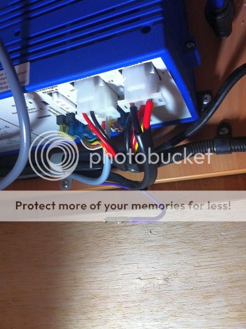
Hopefully there are no other wiring errors elsewhere on the van.  


-- Edited by tempestv8 on Wednesday 4th of February 2015 08:52:09 AM

__________________

2012 A'Van Aspire 499 Adventure pack & 2009 200 Series diesel


Senior Member

Status: Offline
Posts: 157
Date:

Lawrance, I just have a couple of issues.
1. Is your fridge connected through the anderson plug as well? You may want to check it. I had a redarc VSR fitted under the bonnet so that the high current 12v feed is disabled when the motor is not running. Otherwise, the fridge would flatten the tug battery real quick! We had friends who experienced this on their maiden voyage when they just stopped for a coffee!
2. your idea with the trigger wire should work, but it might require the lights be on all the time as I don't know if the EBL charge module internal relay actually latches on, or is held in by the trigger voltage.
3. the tool looks OK. It should push up on the inside, release the clips (or 'fins' or 'tangs') allowing the connector to be removed. As long as the OD of the tool shaft fits neatly into the ID of the plug we're good. Just rotate the tool a bit as you push it in.

I have attached a pix that shows what I ended up doing under my wife's bunk! The little power meter is invaluable - as long as you buy the right one!

Good luck!


-- Edited by Stratman77 on Wednesday 4th of February 2015 01:10:19 PM


-- Edited by Stratman77 on Wednesday 4th of February 2015 01:12:22 PM

__________________

Best regards,

Chris

Licensed Electrician, Electronics, Gaming & Computer Technician. Now retired and loving it!


Senior Member

Status: Offline
Posts: 157
Date:

I have attempted 3 times to attach the pix with no luck. We may have a system problem.

__________________

Best regards,

Chris

Licensed Electrician, Electronics, Gaming & Computer Technician. Now retired and loving it!


Veteran Member

Status: Offline
Posts: 54
Date:

G'day Chris,

Perhaps you could email me the picture so that I can have a look? My email address is "lle66700 @ bigpond . net . au" but without the spaces.

Yes, indeed, thanks for the cautionary word regarding the fridge's 12 volt wiring. I am quite concerned that the Thetford fridge might not be wired to the Anderson plug, which would just flatten the two house batteries within an hour. I have yet to pull off the external vent covers to inspect the wiring. Hopefully the factory has done the right thing.

Will check it out this weekend, if I get a chance. It's getting quite difficult these days for me to spend any appreciable amount of time on these sorts of projects with a little toddler running around needing attention, and a mom who could use a break from looking after him. Yet, the whole reason for the caravan upgrade was for him! Hehe!

Am currently tracking the arrival of this tool that I purchased from the eBay seller in the USA. I searched high and low online and couldn't find an Aussie company supplier. Surely this is a commonly used tool. Hope the one from the USA has the right OD for the job, or I would be no better off when it arrives in a couple of weeks time.

As a side question, where can I buy a plug so that I can use the unused solar input plug (Block 4) on the Elecktroblock? I am about to purchase a folding solar panel (180 Watts). Also, I'm wondering if I should just buy a bigger solar panel (270 Watt) as the prices are not that much different. What are your thoughts on using the Elektroblock to connect to the solar panels? Obviously the A'Van electrician didn't wire it up that way, but connected the roof mounted solar panel directly to the house batteries via the JUTA PWM controller.


EDIT:  Managed to spare a few moments this evening to have a quick look at the fridge electrics.  Just as Chris had cautioned, the fridge is NOT wired to the Anderson plug but directly to the van's batteries.  So even if the tug was connected to the Elektroblock via the Anderson plug, the DC to DC feature will only feed a maximum of 8 Amps of charge to the batteries.  And the fridge would be drawing probably 10+ Amps, so the house batteries will eventually get flattened on a long drive with the fridge turned on.  I have pulled the fuse off so that the fridge will not work on 12 volts, and will rewire the input to the Anderson plug.


-- Edited by tempestv8 on Thursday 5th of February 2015 08:05:53 PM

__________________

2012 A'Van Aspire 499 Adventure pack & 2009 200 Series diesel


Veteran Member

Status: Offline
Posts: 54
Date:

Stratman77 wrote:

I have attempted 3 times to attach the pix with no luck. We may have a system problem.


Here is the photo of Chris' handywork - a complete require of the A'Van's electrics to include a power meter.  Most impressive!


If required, I can also post up the wiring schematics which Chris has kindly shared with me too.


__________________

2012 A'Van Aspire 499 Adventure pack & 2009 200 Series diesel


Veteran Member

Status: Offline
Posts: 54
Date:

After a three week hiatus, the eBay purchased tool has finally arrived. I was very happy with it because I was able to very easily pull out the heavy gauge red wire and put it in the right place.


However the now released purple wire (which kind of looks blue in the picture) is not a positive switched wire.  It turns out to be a negative wire which is somehow wired to the trailer tow plug.

So I can't use this purple wire as the "trigger" wire to turn on the DC-to-DC charging function of the Elektroblock.

Will have to try and out where the other end of that purple wire is.... that's my task for this weekend!

I'm slowly but surely getting there! :)


-- Edited by tempestv8 on Tuesday 24th of February 2015 10:12:21 PM

__________________

2012 A'Van Aspire 499 Adventure pack & 2009 200 Series diesel


Senior Member

Status: Offline
Posts: 157
Date:

Good luck! I wonder what they thought they were doing? One thing is for sure, they didn't really know how the EBL 109 works!

__________________

Best regards,

Chris

Licensed Electrician, Electronics, Gaming & Computer Technician. Now retired and loving it!


Veteran Member

Status: Offline
Posts: 54
Date:

I had some time to spare this evening to have a look at where that purple wire goes.  I traced it back to a scotch lock connector, and the wire that it was connected to was a black wire.  So indeed that explains why the purple wire was an earth wire.

I removed the purple wire from the scotch lock and located some wires which only come live when the lights on the tug are turned on.  I found a pair of brown wires with a scotch lock connector were live when the car lights are turned on.  I am guessing these brown wires could be the live circuits for the external tail lights or the LED corner lights on the caravan's body.  I connected the purple wire to these pair of brown wires, and re attached the pin back onto the Block 2 connector.

I checked the voltage of the house batteries at rest and they were showing 12.9 volts.  Each time I turned on the lights on the tow vehicle (engine idling), the voltage rose to around 13.4 to 13.9 volts.  So I'm very pleased to say the Elektroblock's DC-to-DC charging function is working the way I want it to.  My tow vehicle's lights is the "trigger" signal for the Elektroblock.

What I was really happy about is that the Elektroblock does not have to be turned "on" at the control panel for the DC-to-DC charging to work.  So all the house loads like the ceiling lights, water pump, toilet flush, radio, TV antenna booster, are completely turned off via the main switch, and the tug is replenishing the house batteries.  Fantastic!

A special word of thanks to Chris for his assistance, and my gratitude also for all the other participants on this thread - without which I wouldn't have been able to get a background context to the subject and figured out a successful outcome for my A'Van.  Whoohoo!  Can't wait to go on the next road trip now.  :)


__________________

2012 A'Van Aspire 499 Adventure pack & 2009 200 Series diesel


Senior Member

Status: Offline
Posts: 157
Date:

Great Job, Lawrance! I am still wondering what the heck they (whoever they were who wired it in the first place) thought they were doing?

__________________

Best regards,

Chris

Licensed Electrician, Electronics, Gaming & Computer Technician. Now retired and loving it!


Guru

Status: Offline
Posts: 1615
Date:

Just a question though tempest, is there a particular reason why you only want to charge your caravan battery while the tow vehicle lights are on instead of when the ignition is on?

__________________

Yes I am an agent of Satan, but my duties are largely ceremonial.


Veteran Member

Status: Offline
Posts: 54
Date:

G'day Troopy_03 (Bob?)


You raise a good question - why use the lights on the tug to trigger the DC-to-DC charging function of the Elektroblock?  Here are my thoughts:


When I'm heading off at the commencement of a trip, the van would have been plugged in to domestic 240 volts for a couple of days already.  Mainly to get the fridge nice and cold.  During this period of time, the Elektroblock would also be switched on and hopefully it will have fully charged the van's batteries.  I typically tend to drive off during the day, so there is no need to continue charging the van's batteries.

I was initially keen on using a switched 12-volt source to "trigger" the DC-to-DC charging feature, as per the wiring diagram in the EBL product documentation.  The biggest challenge that I had with that approach was that the 7-pin flat plug trailer plug does not appear to have an ignition switched 12 volt line. I looked at the diagram here:  http://www.exploroz.com/Vehicle/Electrics/TrailerWiringDiagrams.aspx - none of the pins had a switched 12-volt source.  The closest was Pin 7, for rear lights and clearance and side marker lights.


I could have resorted to Chris' solution, i.e. install a delay-timer switch, but I wasn't comfortable with my own electrical skills.  Additionally I didn't want to add complexity to the van's electrics.


So that's why I ended up using the circuit for the clearance and side marker lights as my 12-volt switched source.  Hope that clarifies why I chose this route.


Just as a side note, I don't leave the van connected to domestic power all the time anymore after reading this article:  http://www.atlanticmotorhomeservices.co.uk/schaudt-elektroblock.php  In the section on "how to look after the EBL", point #8 says not to leave the van connected to 240 volts for long periods of time. 


Cheers,


Lawrance


__________________

2012 A'Van Aspire 499 Adventure pack & 2009 200 Series diesel


Guru

Status: Offline
Posts: 1615
Date:

If you don't have reversing lights on your van, and not many do, you could use pin 2 to run your ignition wire through to the van. That's is a common way to do it anyway.

__________________

Yes I am an agent of Satan, but my duties are largely ceremonial.


Veteran Member

Status: Offline
Posts: 54
Date:

Yes, I suppose I could have modified the trailer plug but don't want to touch the electrics on the tug. I did note that this was what Dave (Diggins) did, from his postings.

I may use that reverse pin on the trailer plug for a reverse camera in the future.

As another side note, my LED courtesy light which illuminates the foot well area was smashed (by the previous owner) so I needs to find a replacement.

After much searching, I found the replacement on eBay: www.ebay.com.au/itm/280575168813

That will be my next electrical repair. Also, I found that one of he two 12 volt sockets inside the van does not have any power. More investigations required. Maybe it's a dodgy scotch lock connector somewhere....


-- Edited by tempestv8 on Sunday 1st of March 2015 08:18:47 AM

__________________

2012 A'Van Aspire 499 Adventure pack & 2009 200 Series diesel


Senior Member

Status: Offline
Posts: 157
Date:

Lawrance, my advice with regard to a rear camera is that it is also a great help while travelling as it allows you to see who, how many and how close other vehicles are behind you. The only downside is that you also get to see the rude gestures as well! I installed a cheap little wifi camera kit and it works well as long as you mount the 'sender' on the drawbar. I just connected it to the fridge supply. The wifi saves running a video cable from the back of the van to the driver's seat. If you need more details, just yell. I would suggest you use the reversing lights connection in your tug plug for a reversing alarm instead.

I would agree about your little electrical problem. My roof lights went totally crazy and I found a burnt scotchlok above the rangehood. Don't bother asking Avan for help because they don't know how the van was wired.


-- Edited by Stratman77 on Sunday 1st of March 2015 09:40:00 AM

__________________

Best regards,

Chris

Licensed Electrician, Electronics, Gaming & Computer Technician. Now retired and loving it!


Veteran Member

Status: Offline
Posts: 54
Date:

G'day Chris,

Today, I decided to have a look at Block 3, which is the "house" load plug. To my dismay, the electrician that wired up Block 3 using just used one of the earths on the plug but connected to multiple different devices and simply appended all the earth circuits back to only one pin.


So for example, the positive to the pump is pin 2 (orange wire), but the negative on the pump which should be pin 5 is actually wired to pin 6 (white wire).  When I followed the white wire, I found that the electrician had use it a common ground for quite a number of other house loads, using multiple scotch locks to join all the various earths to that one white wire.


The earth for the water pump should be in pin 5, but there is no wire there.  So what's happening is that the pump's earth is now pin 6 (along with a number of other devices); i.e. posltive from one circuit but negative in a different circuit.  Surely this is not good for the EBL!?  I am wondering whether the EBL will get damaged when positive power is drawn from one circuit but the negative is on a different circuit. I'm sure it's not designed to work like this! 

Am really beginning to concur with the opinion that the electrician who did this job does not know how to wire up the EBL correctly.

I now need to rewire the negative for the pump back to its own circuit, i.e. pump's negative to Pin 5. 

Perhaps this could explain why the ceiling lights were flickering whenever the pump was running! :( :(  So, I will need to source some pins for Block 3, one to insert into the plug for the water pump's negative.

Once I sort out the pump circuit I will systematically work my way through all the other circuits.

It's a rats nest of scotch locks at the moment and I don't know which circuit goes where. I'm going to label the cables, so that I can figure out what's what.


-- Edited by tempestv8 on Sunday 1st of March 2015 03:09:44 PM

__________________

2012 A'Van Aspire 499 Adventure pack & 2009 200 Series diesel


Senior Member

Status: Offline
Posts: 157
Date:

Hi, Lawrance! I wouldn't panic too much as the schematic shows that Block 3 pins 4,5,6,7 & 8 are connected internally to a common -ve 'chassis' connection. Only pin 12 which is the -ve for the fridge controller is not connected internally at all. It looks like that feature is not used in the Avan, even though the other fridge controller connection through pin 9 is 12v+. I sincerely doubt you will achieve anything in a practical sense if you go to all the trouble of making all the -ve connections match the schematic. I understand that Avan, like many van builders sub-contract the electrical installations to the cheapest tenderer, so every production run will have - most likely - a different contractor and tradespeople (obviously not too smart but hopefully qualified) and they will wire it their 'own' way. I think the contractor who wired you van was probably his 12 year old son. There are obviously no quality control checks as your van would certainly not have left the factory as it was. It's hard to get electrocuted by 12vdc, but I am wondering how well your 240v is wired - and how safe. What else did they stuff up that wasn't obvious?

On the subject of Scotchloks (they are not even genuine 3M Scotchloks), I found about 30% were not even fully crimped! Best of British luck trying to trace them all and label them. I think it would be quicker to rewire thew whole van!

Have fun! I found the easiest way to trace the cables is with a 12v test probe (one with a needle point that will test through the insulation) and a long -ve return wire connected to either battery -ve or chassis. Good Luck.


-- Edited by Stratman77 on Sunday 1st of March 2015 03:53:27 PM

__________________

Best regards,

Chris

Licensed Electrician, Electronics, Gaming & Computer Technician. Now retired and loving it!


Veteran Member

Status: Offline
Posts: 54
Date:

Hi Chris,

I wired up the pump directly to the EBL and the lights still flicker when the pump is running.  So this invalidates my theory that the "common" ground on another circuit was the issue.  Instead it validates your comments that it's OK for the positive pin from one circuit being OK to use with different circuit's negative pin. 

I guess the lights flickering when the pump is running must just be normal; perhaps this is a "feature" with 12 volt LED lights.

I will leave the other wiring alone and just enjoy the van. Labour Day long weekend coming up! :)


-- Edited by tempestv8 on Tuesday 3rd of March 2015 12:57:07 PM

__________________

2012 A'Van Aspire 499 Adventure pack & 2009 200 Series diesel


Veteran Member

Status: Offline
Posts: 54
Date:

Just a quick update - for the plastic connectors, I was able to purchase them from A'Van directly, through their spare parts department. The solar plug was about $4 and the connectors for Block 3 & 4 are also available, at a slightly higher price. For PINs, I just go to Jaycar and purchase the pins that are part of a kit for computer power supply plugs, but A'van does also sell them.

__________________

2012 A'Van Aspire 499 Adventure pack & 2009 200 Series diesel


Senior Member

Status: Offline
Posts: 157
Date:

Hi, Lawrance!
Thanks for the update! I knew about the pins from Jaycar, but I would never have thought to ask Avan about the nylon plug! Great work.

__________________

Best regards,

Chris

Licensed Electrician, Electronics, Gaming & Computer Technician. Now retired and loving it!


Guru

Status: Offline
Posts: 1615
Date:

tempestv8 wrote:

Just a quick update - for the plastic connectors, I was able to purchase them from A'Van directly, through their spare parts department. The solar plug was about $4 and the connectors for Block 3 & 4 are also available, at a slightly higher price. For PINs, I just go to Jaycar and purchase the pins that are part of a kit for computer power supply plugs, but A'van does also sell them.


 Just a note on the connector contacts, the contacts in the Electroblok plugs are slightly different to the Molex connector contacts, which are slightly shorter. There are other connectors at Jaycar that have very similar pins to the Mate-n-Lok contacts in the Electroblok and seem to be a better match if you can't get the original AMP Mate-n-Lok contacts. The 12 way connector in the style I'm referring to is part numbered PP2026 in Jayco's catalogue and cost about $7. The connector body isn't any use to you, just use the contacts.

Mate-N-Lok Connector

mate-n-lok.JPG


Jaycar Connector

plug.jpg


Attachments
__________________

Yes I am an agent of Satan, but my duties are largely ceremonial.

«First  <  1 2 3 4  >  Last»  | Page of 4  sorted by
 
Quick Reply

Please log in to post quick replies.

Tweet this page Post to Digg Post to Del.icio.us
Purchase Grey Nomad bumper stickers Read our daily column, the Nomad News The Grey Nomad's Guidebook